SYNC/570i-56 Installation Card SYNC/570i-56 SYNC/570i-56Installation Card SYNC/570i-56
Step 2: Configure the DaughterBoard
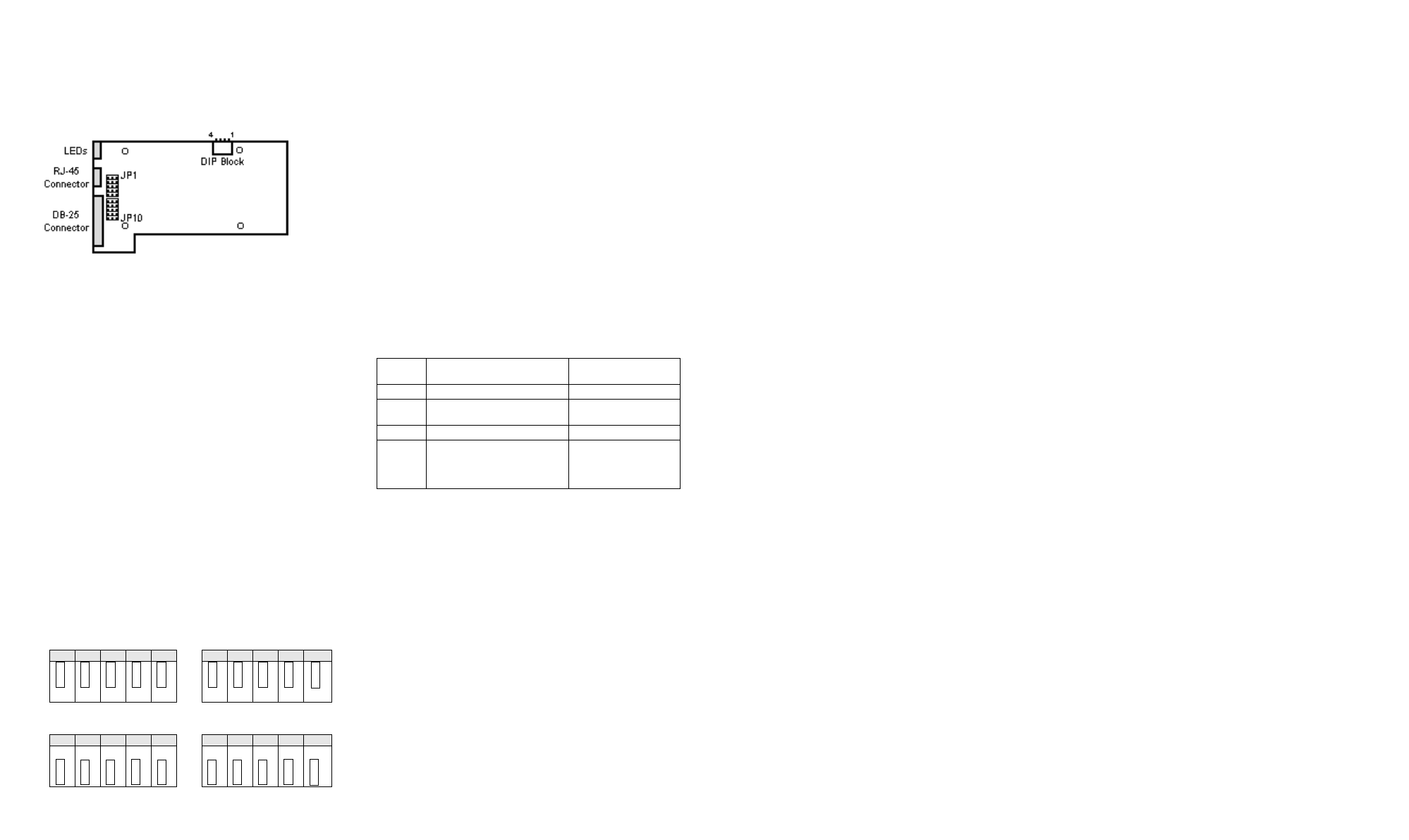
There are two configuration options that must be set
on the daughterboard; the interface port and the CSU/
DSU powerup configuration.
SYNC/570i-56 daughterboard
Configure the Interface Port
The selectable interface port is hardware-configurable
using two jumper sets on the daughterboard.
Note: When disconnecting the daughterboard use
adequate precautions (such as a grounding
wrist strap that is connected to earth ground)
to prevent electrostatic damage.
a. From the host side, remove the metal screws
which secure the daughterboard to the mother-
board.
b. Separate the daughterboard from the mother-
board.
Note: There is one connector holding the daugh-
terboard. Do not pull with a twisting
motion.
c. Install the jumpers for the correct interface.
When the jumpers are on the top two rows, the
interface port is set to V.35. When the jumpers
are on the bottom two rows, the interface port
is set to EIA-232.
Jumper Positions for V.35
Jumper Positions for EIA-232
d. Reconnect the daughterboard to the mother-
board by matching the connectors and screw
wells. Push the daughterboard onto the moth-
erboard and replace the screws.
CSU/DSU Powerup Configuration
The DIP switch that configures the initial powerup
configuration of the CSU/DSU can be changed with
the daughterboard connected to the motherboard.
The initial powerup configuration of the CSU/DSU is
determined by the DIP switch settings. This configu-
ration can be overwritten by AT commands.
This switch can be changed without separating the
daughterboard from the motherboard. With the boards
connected, the OFF label on the switch block is not
visible. OFF is away from the base of the daughter-
board, toward the motherboard.
DIP Switch settings for CSU/DSU Powerup
* Selecting a switched line will automatically choose a 56k
rate with slave timing.
Step 3. Install the adapter in the Computer
Before you Begin
• Record the serial number of the adapter (located
under the part number label). This will enable Digi
to provide you with better service, should the need
arise.
• Shutdown and unplug power from the computer.
• Put a ground strap on to ground yourself. If one is
not available, ground yourself by touching an
unpainted metal surface, such as the computer’s
chassis.
Installation Procedure
1. Remove the computer cover.
2. Locate an available 16-bit slot in your computer
and remove the slot plate.
3. Remove the hold-down screw at the top of the
slot. Remove the slot bracket.
4. Insert the adapter into the slot and screw the end-
plate to the computer chassis. The endplate must
be screwed into the computer chassis to remain in
compliance with Part 15 of FCC rules.
5. Replace the computer cover.
6. Reboot the computer. The LED indicator will dis-
play a steady red light indicating there are no
lines connected.
Step 5. Verify the Installation
The User Diagnostics diskette and the loopback con-
nector are designed to verify correct installation of the
SYNC/570i-56 adapter. When running the diagnostic
program, make sure no devices are connected to the
adapter ports.
1. Boot the system from a DOS-bootable diskette or
partition. The
A:
prompt should display on your
screen.
2. Insert the User Diagnostics diskette.
3. Install the Telco (RJ-45) and EIA-232 loopback
connectors on the adapter.
4. Type
A:\SYNC570
to start the diagnostic pro-
gram.
5. Follow the instructions on the screen.
The diagnostic program displays the current the IRQ,
base memory address, and the base I/O address. You
may modify the address and IRQ selections from the
diagnostic program to test the adapter. The IRQ must
be active and you must select a non-zero address.
Note: For ISA adapters, the following I/O
addresses are not allowed when running
the user diagnostic program; 0x000
through 0x100, 0x1F0, 0x230, 0x240,
0x250, 0x260, 0x270, 0x2e0, 0x2F0,
0x330, and 0x360 through 0x3FF.
The diagnostic tests will fail if there is a memory
address (base I/O address or 16KB memory window)
or interrupt conflict. If the diagnostic program cannot
determine your switch settings, there may be a con-
flict as well. Try changing the memory addresses and
IRQ if the diagnostic program fails.
Other Settings
IRQ and Memory
The memory address and interrupt line (IRQ) are soft-
ware-configurable via either your operating system or
an installable driver. The memory address consists of
a 16KB window.
Fast Select
Jumper JP1 on the ISA SYNC/570i-56 adapter con-
trols the Fast Select circuitry on board. The adapter is
shipped with a jumper connecting pin 2 and pin 3 of
JP1. This option allows the adapter to function with
any combination of 8, 16, or 32 bit video and/or net-
work cards supporting Fast Select.When pins 1 and 2
are jumpered, the adapter must be installed in a
128KB paragraph which contains only 16 or 32 bit
cards. The default setting (pins 2 and 3 jumpered)
works in most computers and should not be changed
without verification from Digi Technical Support.
What Next?
Install and configure the driver for your SYNC/
570i-56 adapter. Consult the DataFire Access
Resource CD for driver installation and configura-
tion procedures. The DataFire Access Resource CD
also contains cabling information, diagnostic and
troubleshooting information, and product features
and specifications.
JP1 JP2 JP3 JP4 JP5 JP6 JP7 JP8 JP9 JP10
ooooo ooooo
ooooo ooooo
ooooo ooooo
JP1 JP2 JP3 JP4 JP5 JP6 JP7 JP8 JP9 JP10
ooooo ooooo
ooooo ooooo
ooooo ooooo
DIP
Switch
OFF ON
1 Leased Line Switched Line*
2 56K Rate
64K Clear Channel
Rate
3 Slave (DDS) Timing Internal Timing
4
&D0 Mode
DTR off: Command Mode
DTR on: Data Mode
&D2 Mode
Dropping DTR ter-
minates a switched
call

 (5 paginas)
 Manymanuals.com
 Manymanuals.de
 Manymanuals.fr
 Manymanuals.it
 Manymanuals.pl
 Manymanuals.cz
 Manymanuals.es
 Manymanuals-pt.com
Comentarios a estos manuales